Integrated Circuit
Basic Electronics Part 2 – Active Components
Integrated circuits are microcircuits that perform special functions. Contained within the IC are very small electronic components which are basically resistors, capacitors, diodes, and transistors. The combination of these components determines the functionality of the IC. The process of transforming electronic components into very small components so as to contain circuitries in very small packages is called integration, thus the name integrated circuit.
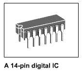
ICs are classified as either linear or digital. Linear ICs are used in analog-type circuits in which there is a continuous variation in voltage or current. Analog circuits include audio amplifiers, operational amplifiers, voltage regulators, and radio-frequency circuits, oscillators, and rectifiers. Digital ICs on the other hand, contain digital circuits or circuits that deal with only two levels for pulses of current or voltage; either High or Low. These include those that are used in computers, digital clocks, calculators, and other digital devices. IC packages commonly come in 3, 8, 14, 16, 24, or 64 pin.
Levels of Integration
ICs are categorized according to their circuit complexity which can be measured by the number of electronic components contained in the package. The process of integration can be classified as small, medium, large, very large, or super large.
Small-Scale Integration (SSI) – SSI devices contain several independent electronic components in a single package. The inputs and outputs are connected directly to the pins in the package. The number of components is less than 10 in every package. Logic Gates like inverters, AND gate, OR gate and etc. are products of SSI.
Medium Scale Integration (MSI) – MSI devices has a complexity of 10 to 100 electronic components in a single package. They usually perform basic and specific digital operations and includes decoders, adders, counters, multiplexers, and demultiplexers.
Large Scale Integration (LSI) – Products of LSI contain between 100 and 10,000 electronic components in a single package. They include memory modules, I/O controllers, and 4-bit microprocessor systems.
Very Large Scale Integration (VLSI) – Devices that are results of VLSI contain between 10,000 and 300,000 electronic components. VLSI produces large memory modules and 8bit, 16-bit, and 32-bit microprocessor systems.
Super Large Scale Integration (SLSI) – This kind is a new type of integration which produces ICs having more than 300,000 electronic components in one package. Examples of devices which use SLSI are 64-bit microprocessor systems and microcontrollers.
Common Kinds of Integrated Circuits
Voltage Regulator – A voltage regulator IC is a three-terminal linear IC which is capable of providing extremely stable voltage supply. Many different voltage regulator ICs that can supply load currents from 100mA to 3A are available commercially. This type of ICs commonly has a feature called thermal shutdown. When the internal temperature of the IC reaches a certain temperature (typically +175 deg. Celsius), the regulator shuts down and prevents the chip from getting any hotter. This protects the IC from excessively high value of heat which may destroy it and damage the connected circuit or load. The LM340 series is a popular series of voltage regulator ICs. They provide regulated voltages of 5, 6, 8, 10, 12, 15, 18, and 24V. Common applications of voltage regulator ICs include power supplies.
Operational Amplifier (OP Amp) – OP Amps are the most commonly used type of linear IC. It is a type of amplifier with a high gain, which means that the ratio of the output to input voltage is in high percentage. Aside from being amplifiers, OP Amps can also be used as voltage comparators.
Logic IC – This type of integrated circuit is the commonly used of all digital ICs. These ICs contain gates which correspond to the logic functions of AND, OR, NAND, NOR, XOR, XNOR, and NOT. Other types of digital ICs are created by creating different combinations of these logic gates.
Multiplexer – A multiplexer is a type of digital IC which contains combinational circuit that selects binary information from one of many inputs and directs it to a single output line (many to one). Multiplexer ICs have select pins that determine which of the many inputs should be selected as the output.
Demultiplexer – Demultiplexer IC is the counterpart of multiplexer IC. It accepts one input and directs the input to many output lines (one to many).
Decoder – Decoder ICs are kinds of digital ICs that are capable of converting binary information to a format which is understandable by humans. For example, the binary digit 0101 can be decoded by a decoder IC and be displayed as a numeric number 5 in a 7-segment display component.
Adder/Subtractor – These are digital ICs that perform the basic operation of binary addition and subtraction. There are no ICs which can perform multiplication and division operations but these mathematical functions can be performed by using Adder and Subtractor ICs along with other ICs like counters.
Flip-flop – Flip-flops are the basic elements of a sequential logic circuit. They are digital devices which produces outputs in reaction to a series of inputs. Unlike logic gates, they do not have predetermined output values because their output depends on the sequence of inputs. Flip-flops are contained in different IC packages.
Counter – Counters are created through the combination of different flip-flops. Counters produces a string of outputs which follows a specific pattern. For example, the output of a counter IC may be from 0000 to 1111 (that is a count from 0 to 15).
Registers – Registers serves a storage of bits of information. They are often associated with clocks and mainly composed of flip-flops. Register ICs come in different packages which have different storage capacities.
Clocks/Timers – These are ICs which are capable of producing signals which could serve as inputs to other ICs or gates. Clock signals are commonly used to synchronize the operations of a sequential circuit.
Previous | Next
3-D Transistors in The Works
June 13, 2006
3-D Transistors in The Works
By David Needle
Intel's researchers are closer to development of processors that use "tri-gate" or three-dimensional transistors, the microscopic, silicon-based switches that process the ones and zeros of the digital world.
The 3D angle is tied to the latest semiconductor research into nanotechnology. At the nanotech level some transistor features may consist of only a few layers of atoms so that what was previously thought of as "flat" is now being designed in three dimensions for improved performance and power characteristics.
Intel plans to make a technical presentation on its research today at the Symposium on VLSI Technology in Honolulu.
Commercial availability is years away, but the development dovetails with the chip industry's increasing focus on more energy efficient design. Intel said tri-gate transistors offer considerably lower leakage and consume much less power than traditional flat or planar transistors.
For example, compared to today's 65 nanometer (nm) transistors, integrated tri-gate transistors can offer a 45 percent increase in drive current (switching speed) or 50 times reduction in off-current, and 35 percent reduction in transistor switching power, according to Intel.
"It's going to be a horse race. People will want to push planar further out so we have to make tri-gate more compelling," Mike Mayberry, Intel vice president and director of component research, told internetnews.com. "It's a friendly competition within Intel that will lead us to best technology."
If adopted, Mayberry said tri-gate transistors could become part of Intel's mainstream processor manufacturing as early as 2009 when the chip giant moves to 32nm manufacturing process. The next transition for Intel comes later this year when it moves from 65nm to 45nm manufacturing. In January Intel showed how its 45nm process development was well underway, showing a fully functional test chip that had over a billion transistors.
The tri-gate design holds significant promise for energy savings. Mayberry said that, while only a small amount of current escapes from today's transistors, the next generation has larger leakage. The tri-gate design is meant to trap most of the current and, in concert with new materials, produce a more energy-efficient transistor.
"In the 1990s we improved efficiency by making devices smaller and lowering the voltage," said Mayberry.
"But it's becoming more of a challenge to lower the voltage as a primary means to decreasing power. We think this latest development allows us to scale and keep up with Moore's Law well into the next decade."
Transistor
Basic Electronics Part 2 – Active Components
Transistors are the most commonly used electronic component. This is because the transistor is very flexible and can perform different functions. It can serve as a switch, an amplifier, or an inverter. Also, combining two or more transistors can produce different effects as with the logic Integrated Circuits (IC). Transistors can be classified into two; bipolar transistors and field-effect transistors (FET).
Bipolar Transistors
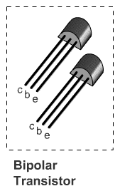
Bipolar transistors are transistors having two junctions. It could be a PNP or an NPN transistor. In operation, the first electrode supplies free charges, either protons or electrons, to be collected by the third electrode at the opposite end, through the middle electrode. The middle electrode controls the current. The first electrode is called the emitter, the second electrode is called the base, and the third electrode is the collector. It must be remembered that the collector and the emitter always has the same type of electrode that is different to that of the base. For example, in a PNP transistor, the base is composed of N-type (negative) material, and the collector together with the emitter is composed of P-type (positive) material.
Emitter – This is the terminal of the bipolar transistor that supplies free charges.
Base – This is the terminal of the transistor that controls the flow of current
Collector – This is the terminal whose function is to collect the charges supplied by the emitter.
Field-effect Transistors (FET)
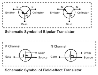
Field-effect transistors function mostly in the same ways as bipolar transistors but they have a different composition. Unlike bipolar transistors, FET’s has a very high input resistance, typically on the range of megaohms, making it capable to take in higher voltage as input signal. The FET operation depends on controlling current through a semiconductor channel which is either N (negative) or P (positive). One side of the channel is the source electrode and the other end is the drain electrode. Current flows from the source to the drain. The voltage applied to the gate electrode controls the current to the channel. An FET is a unipolar device since the charge carriers in the channel have only one polarity.
Source – This is the terminal where the charge carriers enter the channel bar to provide current through the channel. The source corresponds to the emitter in bipolar transistors.
Drain – This is the terminal where current leaves the channel. The drain corresponds to the collector in bipolar transistors.
Gate – This electrode controls the conductance of the channel between the source and the drain. Input signal voltage is generally applied to the gate. The gate is the equivalent of the base in bipolar transistors.
Previous | Next
Diode
Basic Electronics Part 2 – Active Components
A diode is an electronic device having two electrodes; one of which is positive (called the anode) and the other is negative (called the cathode). The node at which these two electrodes meet is called the P-N Junction. Because of having only a single P-N junction, the diode serves as a one-way conductor that allows current to flow only in one direction.
Current flows through a diode only when the diode is in the forward-bias or ON state. This happens when a positive voltage is applied to the anode and the negative voltage is applied to the cathode. During this state, the internal resistance of the diode is very small, that is why current can easily pass through it. On the other hand, when a voltage is applied across the diode such that the anode is connected to the negative voltage and the cathode is receiving the positive voltage, the diode is said to be in reverse-bias OFF state. While in the reverse-bias state, the diode has a very high internal resistance making it impossible for current to pass through it.
The process of allowing current to flow only in one direction is called rectification. One of the most common applications of the diode is rectification. It is often used to convert alternating current to direct current. However, there are different special-purpose diodes which perform more than rectification.
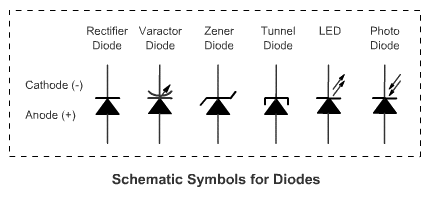
Special-Purpose Diodes
Capacitive or Varactor Diode – Also called varicap, this diode, when operated in reverse-bias, serves as capacitance. The capacitance value is in picofarad. This capacitance can be controlled by varying the reversed input voltage.
Zener Diode – The zener diode is a voltage reference diode. They are used to maintain a fixed amount of voltage. Zener diodes are designed to have a specific reverse “breakdown” voltage. The breakdown voltage is the voltage that the diode can keep constant while operating in reverse-bias. This type of diode is widely used for voltage regulation in dc power supplies.
Tunnel Diode – Also called Esaki Diodes. The important feature of this type of diode is its negative resistance while operating on a certain range of forward voltage. With this characteristic, the diode allows an increase in current when the voltage is decreased. Because of this, the tunnel diode can be used as an amplifier.
Light-Emitting Diode (LED) - The LED is a special-purpose diode that can produce light as current passes through it. Because of this characteristic, the LED is widely used as a basic display component, especially that it requires less power to operate compare to other display units. The typical voltage value needed is 1.6 V to produce 20mA of current. LED’s come in different colors like red, green, blue, yellow, and orange. There are also multi-colored LED’s and blinking LED’s.
Photodiode – This type of diode is made up of photosensitive materials such as sulfide and cadmium, where the resistance decreases with more light. The resistance value without light is called the dark resistance and is typically in the range of megaohms. Being sensitive to light, the photodiode is usually used for many light-control devices.
Previous | Next
Active Components
Basic Electronics
Active electronic components are devices that are capable of controlling voltage or current. The diode, transistor and the Integrated Circuit (IC) are examples of this.
The diode is an active device because current flow and conduction through it depends on the polarity of the input voltage across it. The transistor is an active device because it can amplify the signal and invert or change the direction of current that passes through it. The IC, likewise, is an active device because it is basically a package composed of diodes, transistors, or diodes and transistors.
Previous | Next
Inductor
Basic Electronics Part 1 – Passive Components
An inductor is simply a coil of wire. The basic function is to concentrate the magnetic field of electric current in the coil. More importantly, an induced voltage is generated when the current with its associated magnetic field changes in value or direction. Putting an inductor in a circuit greatly compensates for the sudden change in current that may occur. The voltage across an inductor in a circuit is equal to zero. The effectiveness of an inductor is determined by four factors:
- The number of coils - More coils means more inductance.
- The material that the coils are wrapped around or the so-called core
- The cross-sectional area of the coil - More area means more inductance.
- The length of the coil - A short coil means narrower (or overlapping) coils, which means more inductance.
A transformer is composed of two or more coil windings. Induced current is produced when there is a current change in any of the windings. The purpose of the transformer is to increase or decrease the amount of voltage between the windings. The transformer, however, operates in AC (Alternating current) voltage only.
The symbol for inductance is L, for the linkages of the lines of force in the magnetic field. The unit is in Henry (H).
Inductors in Circuit Connections
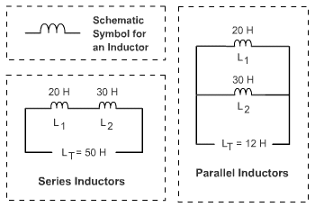
The result of combining inductors in a circuit is similar to combining resistors. For a series connection, the amount of inductance L is increased. For a parallel connection, inductance is decreased.
In a series connection, the total inductance is obtained by adding the individual capacitance values of the connected capacitors (Lt = L1 + L2 + Ln). In a parallel connection, the total inductance is equal to the reciprocal of the sum of the reciprocal values of the capacitors (1/Lt = 1/L1 + 1/L2 + 1/Ln).
When dealing with a series-parallel connection, the inductance is obtained by applying the rules in series and in parallel connections one after another.
Previous | Next
Capacitor Values
Basic Electronics Part 1 – Passive Components
Determining Capacitor Values
The value of the capacitance in a capacitor can be determined by reading the prints in the capacitor. Often, high-capacitance capacitors, like electrolytic caps, have their values written explicitly in their casing; for example, 22 μF (Twenty two microfarads). However, smaller-valued capacitors have codes printed on them and not their actual value. This is because they usually come in very small sizes.
The code is usually a two-digit or three-digit code. The two-digit code plainly represents the capacitance value in picofarads (pF). For example, a ceramic capacitor that has “22” printed on it would simply mean that it has a capacitance of 22 pF. For the three-digit code, the first two digits are the significant digits and the third digit is the multiplier. As with the two-digit code, we read the values in the three-digit code in pF. For example, a ceramic capacitor that is printed with “104” has a capacitance of 10 x 10000 or 100,000 pF or 0.1 μF. It must be noted that the digits “6” and “7” are not used in the code.
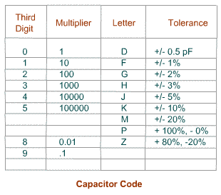
Sometimes the code comes with a letter, say 104K. This letter represents the tolerance in the capacitance rating of the capacitor. For example, the 104K capacitor has a capacitance of 100,000 pf +/- 10%. That’s capacitance ranging from 90,000 pF to 110,000 pF.
Capacitors in Circuit Connections
Like resistors, two or more capacitors can be combined to obtain the desired capacitance value. When combining capacitors in a series connection, the capacitance is decreased, while in a parallel connection the capacitance is increased. This is the opposite of what happens when we combine resistors.
In a series connection, the total resistance is equal to the reciprocal of the sum of the reciprocal values of the capacitors (1/Ct = 1/C1 + 1/C2 + 1/Cn). In a parallel connection, the total capacitance is obtained by adding the individual capacitance values of the connected capacitors (Ct = C1 + C2 + Cn).
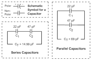
In a series-parallel connection, the rules for obtaining capacitance values in series and in parallel are applied successively.
Previous | Next
Capacitor
Basic Electronics Part 1 – Passive Components
A capacitor is a passive electronic component which can store electrical charges. It consists of two (2) conducting plates and separated by an insulating material. This insulating material is also called the dielectric material. The capacitor’s basic function is to concentrate the electric field of voltage applied across the dielectric so that it can store and accumulate charge coming from the voltage source. Then the stored energy can be discharged by the dielectric when the charging source is replaced by a conducting path.
Because of this characteristic, the capacitor continuously charges and discharges when AC (Alternating Current) voltage is applied to it. While on the other hand, when DC (Direct Current) voltage is applied to it, the capacitor acts as an open circuit which charges completely and never discharges unless the DC voltage source is replaced by a load (a conducting path or a circuit). The current along a capacitor in a circuit is equal to zero.
The unit of capacitance is Farad (F) but one Farad (1 F) is too much for circuit applications. Because of this commercially available capacitors come in microfarads (μF or picofarads (pF).
Voltage Rating
Capacitors have corresponding voltage ratings that specify the maximum voltage that can be applied across the plates without destroying the dielectric. A voltage rating higher than the actual potential difference applied across the capacitor is recommended for safety purposes when creating circuits or electronics applications.
Polarized and Non-polarized Capacitors
Capacitors can be categorized as either a polarized capacitor or a non-polarized capacitor. A polarized capacitor is a type of capacitor that requires polarity when connected in a circuit. Its two leads cannot be interchange and can only be connected one way in a circuit. The positive lead is usually longer than the negative lead. In some capacitors, a stripe in the casing tells where the negative lead is. A non-polarized capacitor is a type of capacitor that can be connected with its two terminals in either position. Ceramic, mica, and mylar capacitors are examples of this.
Types of Capacitors
Capacitors come in different packages to suit different applications.
Electrolytic Capacitors - Made of electrolyte, electrolytic capacitors are the most common type of polarized capacitor. It is commonly used for Ripple filtes, and timing circuits. Although not very accurate and suitable for high frequency circuits, electrolytic capacitors are cheap and are readily available in very small or very large values in μF.
Ceramic Capacitors - Constructed with materials such as titanium acid barium for the dielectric. Internally these capacitors are not constructed as a coil, so they are well suited for use in high frequency applications. Typically used to by-pass high frequency signals to ground. They are shaped like a disk, available in very small capacitance values and very small sizes. The most commonly used type of non-polarized capacitor. Like the electrolytic, it is cheap and easily available.
Tantalum Capacitors - Made of Tantalum Pentoxide. They are electrolytic capacitors but used with a material called tantalum for the electrodes. It is superior to electrolytic capacitors having excellent temperature ranges and frequency characteristics. Tantalum capacitors are expensive and easily damaged by spikes in the circuit.
Super Capacitors - The Electric Double Layer capacitor is called a super capacitor because of its capacitance value that is 0.47 Farad (470,000 µF). Despite the large capacitance value, its physical dimensions are relatively small. It has a diameter of 21 mm and a height of 11 mm. Like electrolytic caps the super capacitor is a type of polarized capacitor.
Polypropylene Capacitors - The polypropylene film is the dielectric used in this type of capacitor. Can be used in applications within a frequency range of 100KHz. Polypropylene caps has a tolerance of about 1% and are available in very small values.
Polyester Film Capacitors - This capacitor uses a thin polyester film as a dielectric. Polyester film caps are cheap and are stable with temperature changes. They are also readily available and are widely used. Tolerance is approximately 5% to 10%.
Polystyrene Capacitors – Uses Polystyrene as the dielectric. This type of capacitors are often used in filter circuits or timing applications and are not suited for high frequency circuits. Metalized Polyester Film Capacitors - Dielectric made of metalized Polyester or "Mylar". These capacitors are stable with temperature change and can come in very small physical sizes.
Epoxy Capacitors - Created using an epoxy dipped polymers as a protective coating. Epoxy capacitors are widely available, stable, and cheap. Can be quite large depending on capacity or rated voltage and so may not be suitable for all applications.
Mica Capacitors – Uses Mica as the dielectric. Often used in creating resonance circuits, frequency filters, and military devices. This type of capacitor is highly stable and very durable making it expensive.
Previous | Next
Resistor
Basic Electronics Part 1 – Passive Components
Resistance is an opposition to current. The amount of resistance determines how much current can flow through a material. The greater the resistance, the less current can flow. Air, for example, has an almost infinite resistance making it very difficult to conduct electricity through it. Metals, on the other hand, have very low resistance values making them effective conductors. Resistance values are measured in ohms (Ω). Resistors are components that have predetermined resistance values. Commercially available resistors come in different packages; carbon film resistors, metal film resistors, wire-wound resistors, chip resistors and precision resistors. Of theses variations, the carbon resistors are the commonly used for many electronics applications. Resistors have resistance values ranging from 0.5 Ω to 10 MΩ (10 million ohms).
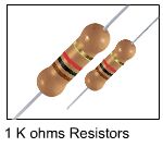
Determining Resistor Values
The resistance value of a resistor is determined by reading its color code. Resistors usually come in package having four (4) colored stripes. The first two colored stripes represent the significant digits, the third colored stripe represents the multiplier digit, and the fourth colored stripe tells the percentage of tolerance in the resistance value. It is easy to determine which stripe in a resistor is the first stripe because the color of the first stripe cannot be silver or gold.
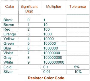
A resistor that has Yellow-Violet-Orange-Gold stripes has a resistance value of 47KΩ (47, 000 ohms). That is 47 (Yellow-Violet) multiplied by 1000 (Orange). But since it has a 5% tolerance (Gold) and 2350 is 5% of 47K, its actual resistance value ranges from 44,650 ohms to 49350 ohms (47,000 +/- 2350).
Power Rating
Another important characteristic of a resistor is its power rating. The power rating specifies the maximum power the resistor can dissipate without excessive heat. Too much heat burns the resistor thus causing damage to a certain circuit. To avoid this, it is advisable to use a resistor that has a greater wattage rating than the actual power dissipation. Carbon resistors have a wattage rating of 1/4 watt, 1/2 watt, and 1 watt. The higher resistance value the resistor has, the lower is its power rating since it cannot have great amount of current. The lower the power rating, the smaller is the actual physical size of a resistor.
Variable Resistors
Resistors are also packaged in such a way that their resistance values can be calibrated. These resistors are called variable resistors. Variables resistors are very useful when experimenting with circuits, especially when the needed resistance values cannot be precisely determined.
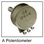
Rheostats and potentiometers are examples of variable resistors. A rheostat has two terminals which are to be connected in series to a load. The common purpose of using a rheostat is to vary the amount of current. A potentiometer, on the other hand, has three terminals. A common application of the potentiometer is to vary the voltage in a circuit. The two ends of the potentiometer are connected across a voltage source. Then the variable arm is adjusted to vary the voltage division between the center terminal and the end terminals.
Resistors in Circuit Connections
Two or more resistors can be combined to obtain the desired resistance value or power rating. Resistors can be combined in series, parallel, or series-parallel. Combining resistors in series connections increases the resistance value, while combining the same resistors in parallel connection decreases the resistance value. The power rating increases whether the resistors are connected in series or in parallel; and is equal to the sum of the individual power rating of the resistors.
In a series connection, the total resistance is obtained by adding the individual resistance values of the connected resistors (Rt = R1 + R2 + Rn). In a parallel connection, the total resistance is equal to the reciprocal of the sum of the reciprocal values of the resistors (1/Rt = 1/R1 + 1/R2 + 1/Rn).
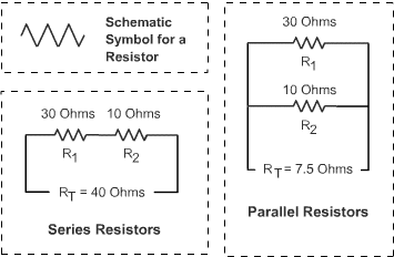
When dealing with a series-parallel connection, the rules for obtaining resistance values in series and in parallel are used successively.
Previous | Next
Passive Components
Basic Electronics
Passive devices are electronic components that do not have the capability to generate voltage or control current but serves as mediums through which current could flow or voltage may be stored. Resistors, Capacitors, and Inductors are all passive components having their own unique characteristics.
Resistors reduce the amount of current. Resistors provide a voltage drop equal to the product of the current and its resistance (V = IR). Capacitors are capable of charging and discharging in reaction to changing voltage. And Inductors produces magnetic field for alternating current.
Next
About Electronics Kit
Electronics Kit is an online resource for electronics students, hobbyists, and professionals. Electronics Kit features lessons and tutorials about analog and digital electronics, and a collection of circuit projects and schematic diagrams. The site also offers electronics-related articles and updates.
Electronics Kit is owned and maintained by Victorio S. Duran III, a computer engineering student at Polytechnic University of the Philippines. (e-mail: vsduran@gmail.com)


