Resistor
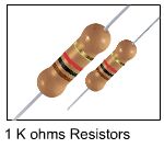
Basic Electronics Part 1 – Passive ComponentsResistance is an opposition to current. The amount of resistance determines how much current can flow through a material. The greater the resistance, the less current can flow. Air, for example, has an almost infinite resistance making it very difficult to conduct electricity through it. Metals, on the other hand, have very low resistance values making them effective conductors. Resistance values are measured in ohms (Ω). Resistors are components that have predetermined resistance values. Commercially available resistors come in different packages; carbon film resistors, metal film resistors, wire-wound resistors, chip resistors and precision resistors. Of theses variations, the carbon resistors are the commonly used for many electronics applications. Resistors have resistance values ranging from 0.5 Ω to 10 MΩ (10 million ohms).
Determining Resistor Values
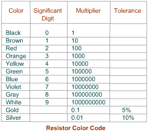
A resistor that has Yellow-Violet-Orange-Gold stripes has a resistance value of 47KΩ (47, 000 ohms). That is 47 (Yellow-Violet) multiplied by 1000 (Orange). But since it has a 5% tolerance (Gold) and 2350 is 5% of 47K, its actual resistance value ranges from 44,650 ohms to 49350 ohms (47,000 +/- 2350).
Power Rating
Another important characteristic of a resistor is its power rating. The power rating specifies the maximum power the resistor can dissipate without excessive heat. Too much heat burns the resistor thus causing damage to a certain circuit. To avoid this, it is advisable to use a resistor that has a greater wattage rating than the actual power dissipation. Carbon resistors have a wattage rating of 1/4 watt, 1/2 watt, and 1 watt. The higher resistance value the resistor has, the lower is its power rating since it cannot have great amount of current. The lower the power rating, the smaller is the actual physical size of a resistor.
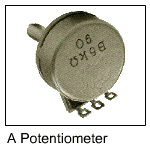
Variable Resistors
Resistors in Circuit Connections
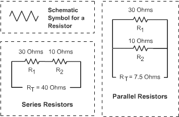
Two or more resistors can be combined to obtain the desired resistance value or power rating. Resistors can be combined in series, parallel, or series-parallel. Combining resistors in series connections increases the resistance value, while combining the same resistors in parallel connection decreases the resistance value. The power rating increases whether the resistors are connected in series or in parallel; and is equal to the sum of the individual power rating of the resistors.
When dealing with a series-parallel connection, the rules for obtaining resistance values in series and in parallel are used successively.
Previous | Next


0 Comments:
Post a Comment
<< back to Home